Indoor LED Displays
Narrow-pixel-pitch and venue formats for close viewing, controlled lighting and detailed content.
Review systems →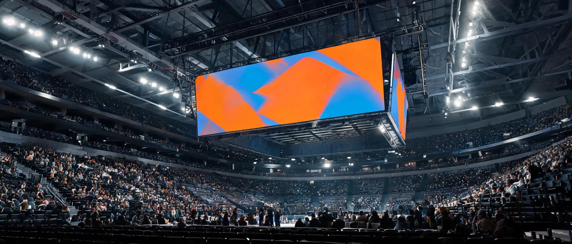
Plan pixel pitch, brightness, controls and service access as one system—from the first sightline study through commissioning and lifecycle support.
The values below summarize Daktronics' published indoor LED display specifications. Final values vary by product family, configuration and test condition; confirm the project submittal before procurement.
| Selection factor | 4 mm reference | 6–20 mm reference |
|---|---|---|
| Pixel configuration | RGB 3-in-1 SMD | RGB 3-in-1 SMD |
| Rule-of-thumb viewing distance | About 12 ft at 3× pitch | About 18–60 ft at 3× pitch |
| Published horizontal viewing angle | 170° | 170° |
| Published vertical viewing angle | 170° (+85°/−85°) | 140° (+60°/−80°) |
| Published half-brightness lifetime | 100,000 hours | 100,000 hours |
Source anchor: Daktronics “Indoor LED Video Displays” specifications and “How to Determine Optimal Viewing Distance?” support guidance, accessed July 2026.
Narrow-pixel-pitch and venue formats for close viewing, controlled lighting and detailed content.
Review systems →High-output display assemblies planned around ambient light, weather exposure and service access.
Review systems →Message centers and visual communication endpoints connected to scheduled content workflows.
Review systems →Controllers, signal paths and operating practices coordinated with the display and the room.
Review technology →Compliance is model- and market-specific. The review path should identify the exact safety listing, electromagnetic requirements, structural submittals and acceptance criteria applicable to the installed configuration.
Confirm listing and installation conditions by model.
Coordinate emissions and immunity requirements by region.
Align cabinet loads, mounting and site engineering.
Document calibration, signal and operational checks.
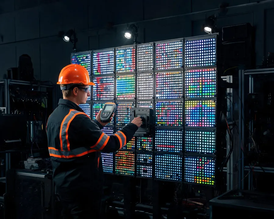
Smaller pitch supports closer viewing; larger pitch can be appropriate when the audience is farther away.
A specification should consider daylight, room lighting and content—not select the highest number by default.
Front or rear access, lift zones and spare-module handling affect structure, wall depth and operating cost.
Define uniformity and calibration checks before installation so expectations can be tested at handover.
Review representative text, motion and camera content at the expected viewing distance before final sign-off.
We will turn those inputs into a reviewable display brief with test points and lifecycle considerations.